

Why won't my 3D file slice, and how do I fix it?
On this page
- Holes in the mesh: not watertight (non-manifold)
- Faces point the wrong way (flipped normals)
- Walls with no thickness
- Extra shells or overlapping bodies
- Curves come out faceted (export resolution)
- Wrong units: a part 25.4 times too small or too big
- How to repair an STL or mesh in your CAD or slicer
- Still won’t slice? Send it and we check it
- Frequently asked

A 3D file usually won’t slice because its mesh is not a closed solid, and the slicer flags it as non-manifold or says the mesh has errors. A slicer, the software that turns a model into printer moves, has to know what is inside the part and what is outside. A hole, a face pointing the wrong way, a wall with no thickness or a stray extra shell takes that away. Below is each mesh error, what it looks like and how to repair it, plus two export mistakes that spoil the print: coarse curves and the wrong units.
Most files are drawn as exact solids in CAD (computer-aided design) software and saved as a mesh: thousands of small flat triangles covering the surface (STL, 3MF or OBJ). The faults below creep in at that step, or come with models downloaded or scanned. For which format to send and how to name it, see how to export and send a 3D file.
Holes in the mesh: not watertight (non-manifold)
A watertight mesh, also called manifold, closes all round like a balloon: every edge is shared by exactly two triangles. A hole breaks that. It may be one missing triangle, a whole missing patch that you can see straight through, or two surfaces that almost meet but leave a hairline gap.
- What you see: the slicer warns of open edges or a non-manifold mesh, or layers go missing or fill in across a gap.
- Where it comes from: surfaces in CAD that were never joined into a solid, a scan with missing patches, or a model built for a game or a render rather than for printing.
- The fix: close the gap in your CAD software (join or stitch the surfaces into one closed solid) and export again, or run your slicer’s repair command for a small hole. In Fusion, the Mesh tab’s Prepare > Repair command closes holes in a mesh body.
Faces point the wrong way (flipped normals)
Every triangle in a mesh carries a direction, its normal, that marks which side is outside. A flipped face points inwards instead: its outside faces the inside of the part, so the slicer reads that patch as inside out and may leave it empty or fill the wrong side.
- What you see: in many viewers a flipped patch shows darker, or in a different colour, from the rest of the model.
- Where it comes from: surfaces mirrored or drawn in the wrong order, often in modelling software meant for animation.
- The fix: use your software’s command to recalculate, unify or flip normals so every face points outwards (in Blender, Mesh > Normals > Recalculate Outside), then export again.
Walls with no thickness
A wall drawn as a single surface has no inside, so there is nothing to print. It looks solid on screen but has no thickness at all. It is a common fault in architectural models and in shapes built from flat sheets, where walls, fins or signs are drawn as planes.

- What you see: the wall disappears in the sliced preview, or the slicer reports the model as empty.
- The fix: give every wall a real thickness with your software’s shell, thicken or offset command (Thicken in Fusion, OffsetSrf with the Solid option in Rhino, the Solidify modifier in Blender), so it becomes a closed solid.
- How thick: the minimum wall depends on the process. The rules at a glance gives it for filament, resin, nylon and metal printing.
Extra shells or overlapping bodies
A shell is one closed piece of mesh. One part should usually be one shell, and extras confuse the slicer or print as loose bits.

- Overlapping bodies. Two solids pushed into each other but never joined. The slicer may print the overlap twice or leave a seam inside the part. Join (union) them into one before you export.
- Stray shells. Loose bits left in the file: a construction surface, a tiny fragment, a hidden copy of a body, or a part inside another. Delete them.
- Separate parts on purpose. If the file really holds several parts, export each as its own file, as the export checklist explains.
Curves come out faceted (export resolution)
When CAD software saves an STL or 3MF, it turns every curve into flat triangles. Too coarse, and a round knob prints as a polygon you can see and feel. Much too fine, and the file grows huge with no gain on the print, sometimes past the 1 GB upload limit.

- Export fine enough that curves look smooth. Zoom in on the exported file, not the drawing: if a curve shows flat steps there, it will print with them. A “fine” or “high” preset in your CAD software is a sensible starting point.
- Save STL as binary, not text (ASCII). Binary holds the same shape in a much smaller file.
- STEP and IGES skip this step, because they store the exact curve rather than triangles.
Wrong units: a part 25.4 times too small or too big
An STL or OBJ file stores numbers with no unit, so a part drawn in inches arrives 25.4 times too small, with walls too thin to slice, and the opposite mistake makes it too big for the printer. The units step in the export checklist shows how to set millimetres before you export.
How to repair an STL or mesh in your CAD or slicer
Most faults are quicker to fix in the software that made the model than in the mesh afterwards, because a fix there carries into every future export.
- Check before you export. Most CAD packages have a check command for open edges or invalid solids: in Rhino, ShowEdges finds open (naked) edges and Check reports a bad object.
- Repair the mesh. Most slicers repair small faults when a file loads, and many have a repair command for more. Blender’s free 3D Print Toolbox finds holes, faces that point the wrong way and walls too thin to print.
- Look at the sliced preview. Step through it layer by layer for missing walls, empty tops and loose bits before you trust the file.
- Fix at the source when you can. A repair command guesses at what you meant, and a large repair can change the shape. If it does, go back to the model.
Still won’t slice? Send it and we check it
You do not have to fix every fault yourself. Upload the file as it is and tell us what the slicer said. A person checks every file before it prints: they look for holes, flipped faces, walls with no thickness, wrong units and coarse curves, and tell you before anything is made.
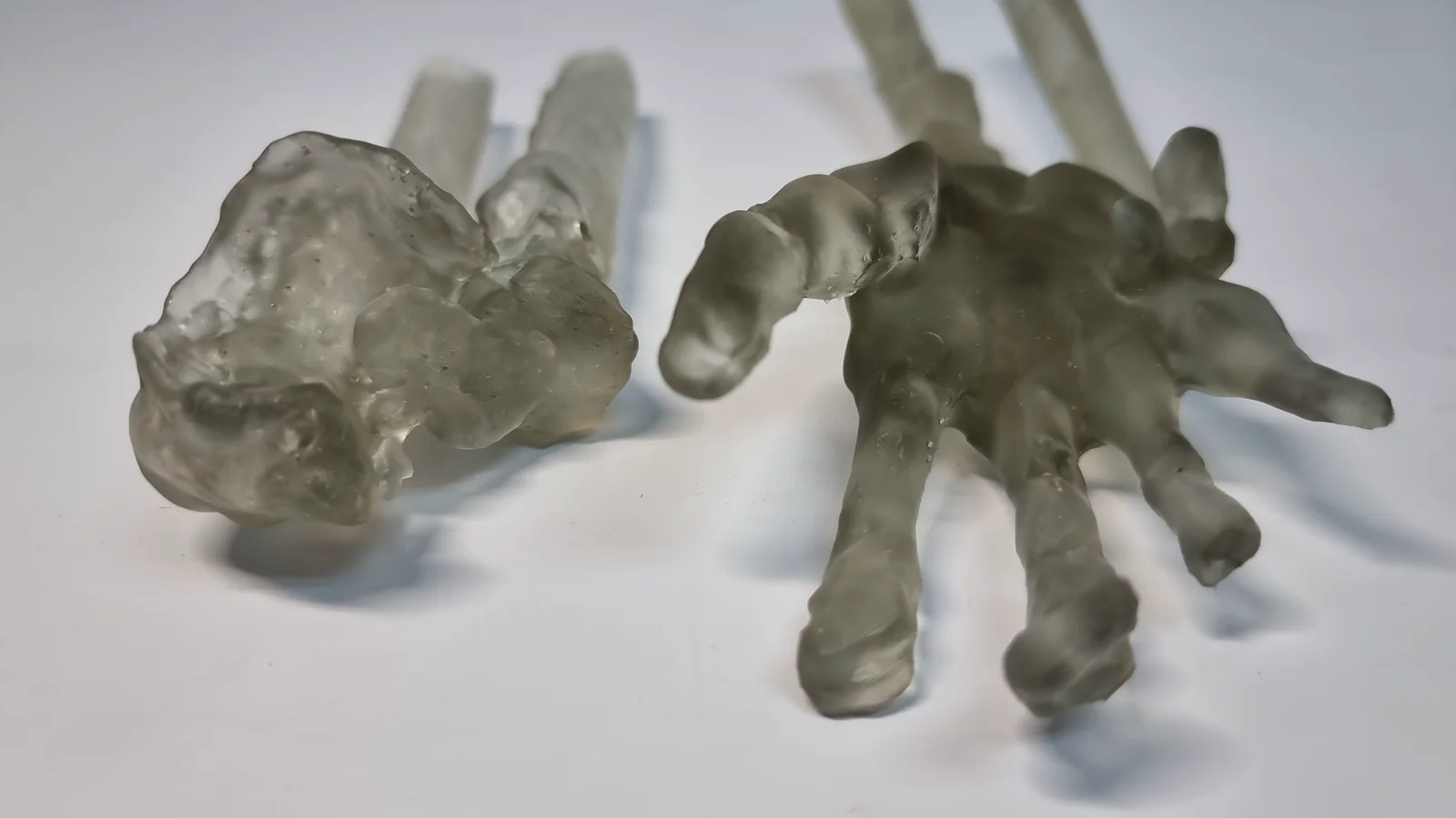
If the model needs more than a tweak, our design service can redraw it, or build one from a sketch, a scan or a sample if you have no usable file.
Frequently asked
Why won't my 3D file slice?
A 3D file usually won't slice because the mesh is not a closed solid. The common mesh errors are a hole in the mesh, flipped faces, walls drawn as a single surface with no thickness, and overlapping bodies or stray shells never cleaned up. Wrong units can also leave features too small to slice. Your slicer's repair command fixes many of these, or you can repair the STL in the software that made it; if it still fails, send it and a person will look at it.
What does watertight (manifold) mean in a 3D file?
A watertight mesh is a surface closed all round, like a balloon, with every edge shared by exactly two triangles. Manifold means the same thing. Without it the slicer cannot tell the inside of the part from the outside, so walls go missing or the file will not slice at all.
My slicer says the model is non-manifold. Will it still print?
A model the slicer calls non-manifold sometimes still prints, but do not ignore the warning. Non-manifold means some edges are shared by one triangle, or by three or more, instead of exactly two. Slicers often patch small faults on their own, so the file may slice, but the patch is a guess. Look through the sliced preview layer by layer, and fix the model if any wall or top surface is missing.
What are flipped faces, or flipped normals?
A flipped face is a triangle whose outside points inwards. Every triangle in a mesh carries a direction, its normal, that marks which side is outside, and a flipped one makes the slicer read that patch as inside out. Most CAD and mesh tools have a command to recalculate or unify normals that fixes it.
Why does part of my model disappear in the slicer preview?
A part that vanishes in the preview usually has no thickness or no closed surface. A wall drawn as a single surface, a hole in the mesh or a patch of flipped faces gives the slicer nothing solid to fill, so it skips that part. Give the wall a real thickness, or close the gap, and export again.
Why do the curves on my print look faceted?
Faceted curves mean the file was exported too coarse, so each curve was saved as a few flat triangles and printed that way. Raise the export resolution, often a "fine" or "high" preset, until curves look smooth when you zoom in on the exported file. A STEP or IGES file avoids this, because it stores the exact curve.
Why is my STL file so big?
An STL file is usually big because it was exported finer than the print needs, saved as text (ASCII) instead of binary, or still holds hidden parts inside the model. Save as binary, delete what you cannot see, and lower the export resolution a step if curves still look smooth. The Additive Inn instant quote takes uploads up to 1 GB.
Can the wrong units stop a file slicing?
Yes, the wrong units can stop a file slicing or spoil the print. A part drawn in inches and read as millimetres arrives 25.4 times too small, so a 2 mm wall becomes less than 0.1 mm and is too thin to print. The opposite mistake makes a part 25.4 times too big for the printer. Export in millimetres, or send 3MF, STEP or IGES, which record their units.
Should I repair the STL myself or send it as it is?
Try your software's check or repair command first, because a fix in your own model carries into every future export. If the fault is not clear or the repair breaks the shape, send the file as it is and tell us what the slicer said. A person checks every file before it prints and tells you what needs changing.
Can you fix my file for me?
Yes, a person checks every file before it prints and tells you what needs fixing, such as a hole in the mesh or flipped faces. If the model needs more than a tweak, such as walls with no thickness throughout, our design service can redraw it, or build one from a sketch, a scan or a sample if you have no usable file.
Related
-
 GuideWhere can you get free 3D files to print?
 -
 GuideHow do you prepare a 3D model so it prints properly?
 -
 GuideWhat are the most common problems with 3D printed models?
 -
 ServiceIndustrial 3D Printing
 -
 ServiceConcept to Fabrication
 -
 ServiceProduct Development & Prototyping
 -
 ProjectArchitectural Concept Model
 -
 ProjectRealistic Lizard Replica
 -
 ProjectCouple Model Replication