

How do I design an architectural model for 3D printing?
Updated
On this page
- Wall thickness and details at model scale
- Choosing a scale for an architectural model
- Preparing the file from SketchUp, Rhino or Revit
- Orienting a building model on the print bed
- Splitting a building into floors and wings
- Joining and finishing the model
- When to switch to resin (stereolithography, SLA)
- Frequently asked
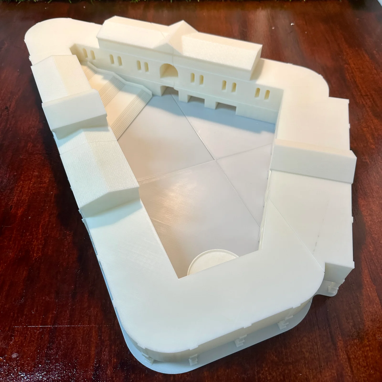
An architectural model for filament printing (fused deposition modeling, FDM) needs every detail that must show at least 1 mm thick at model scale, and walls of 1.2 mm (2.0 mm where it is handled or glued). The file must be a closed, watertight solid, and a building bigger than the printer is split by floor or wing. This guide shows how to check that at your scale, prepare the file from SketchUp, Rhino or Revit, then orient, split and finish the building, using models from our Singapore studio. Or hand the whole model to the Additive Inn scale model team.
Wall thickness and details at model scale
Shrinking a building shrinks every wall, frame and rail with it, and the printer has a limit. It builds in fine lines of melted plastic, so a detail thinner than 1 mm on the model drops out or prints as one wobbly strand.
The sum: real size in millimetres, divided by the scale number, is the size on the model. A 200 mm wall at 1:100 becomes 2 mm and prints. A 50 mm door frame at 1:100 becomes 0.5 mm, half the minimum, and at 1:200 it is 0.25 mm.

The minimums for a 3D printed scale model in filament:
- Smallest detail: 1 mm at model scale. A mullion (the bar between window panes), a balcony rail or a door frame has to be at least 1 mm thick on the model to print.
- Walls: 1.2 mm, and 2.0 mm on anything handled, glued or lifted off: the base, a removable floor, a column glued in.
- Openings: at least 2.0 mm across for windows and doors.
- Signage: strokes of 1.0 mm and letters 5 mm tall read at arm’s length.
Exaggerate, don’t drop. Thicken a detail to 1 mm rather than leave it true to scale or delete it. From viewing distance a door frame drawn a little heavy still reads as a door frame; a facade with its frames missing reads as a blank wall.
Long, thin uprights are the hardest case. Railing posts and slender columns printed standing up wobble as the nozzle works on them, so thicken them to at least 1 mm, or print a railing as a flat panel and fit it afterwards.
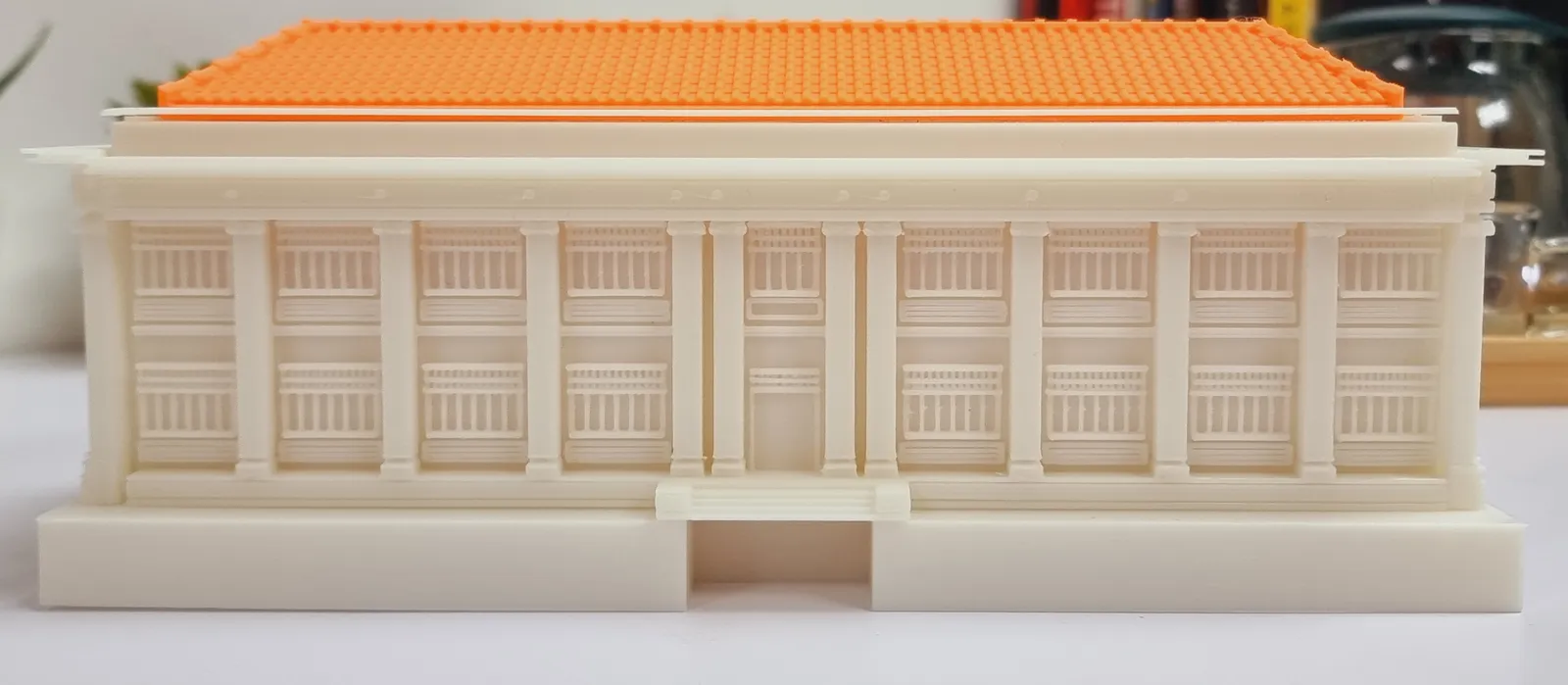
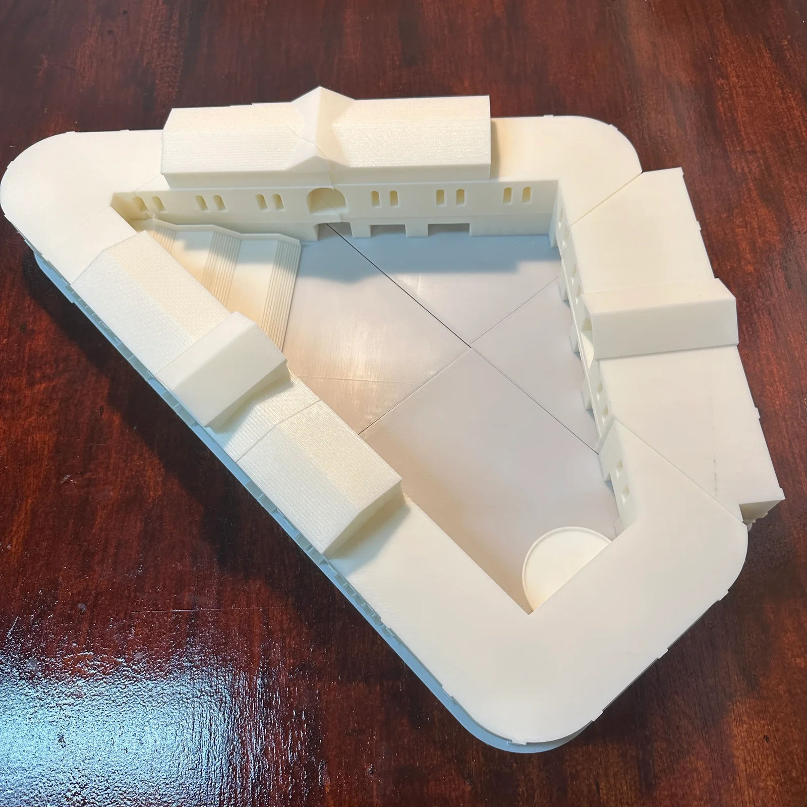
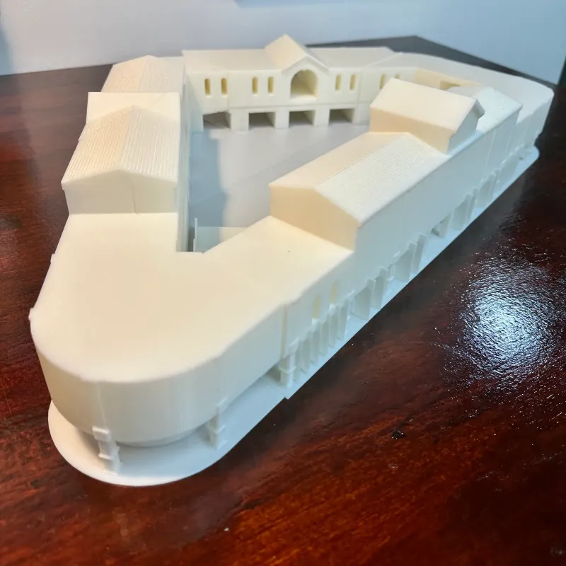
Kept thick enough, fine architecture prints well in filament: the colonnade, arched windows and entrance below are all part of one of our concept models.
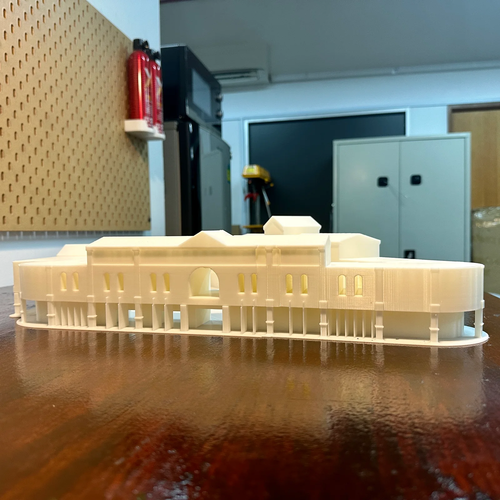
Thin walls, sagging overhangs and the other defects that can hit any filament print are in FDM print defects that start in the design, and every process’s figures sit side by side in the design rules table.
Choosing a scale for an architectural model
Scale trades the size of the model against the smallest detail it can carry. Pick the scale at which the smallest detail that matters is still 1 mm thick, or plan to thicken it.
The scales below are the ones architects typically use for each job, a common starting point rather than a rule. Your brief or your display space may call for another.
| Scale | Typically used for | 1 mm on the model is (real) |
|---|---|---|
| 1:50 | Interiors | 50 mm |
| 1:100 | One building | 100 mm |
| 1:200 | A block | 200 mm |
| 1:400 or 1:500 | A site | 400 to 500 mm |
| 1:1000 | A masterplan | 1 m |
The last column is the thinnest real feature that survives at that scale without being thickened. At 1:100, a 100 mm mullion just prints; at 1:500, nothing thinner than half a metre does, so a site model shows massing, not window frames.
Size counts too. At 1:100, 36 m of building is 360 mm of model, the most our desktop printers take in one piece. Our large-format printer takes up to 1000 x 1000 x 1200 mm, and anything bigger is split (see below).
Preparing the file from SketchUp, Rhino or Revit
The most common problem in an architect’s file is a wall with no thickness. SketchUp faces, Rhino surfaces and many Revit exports describe a wall as a single sheet: it looks solid on screen, but a printer cannot print a sheet. Give every wall real thickness, 1.2 mm or more at model scale, before anything else.

The model also has to be watertight: closed all round, like a balloon with no holes, so the slicer (the software that turns a model into printer moves) can tell inside from outside. Why a 3D file won’t slice shows how to find and close holes, and the file checklist covers each check in one line.
- SketchUp: make each part a solid group or component, and delete stray lines and doubled faces inside walls.
- Rhino: join each part into a closed polysurface, and check it shows no naked edges (edges left open, a sign of a gap) before you export.
- Revit: export the massing and the facade you want to show; leave out furniture, pipes, ducts and anything hidden inside.
- Interiors: delete what nobody will see, unless a floor lifts off to show it. Hidden detail only makes the file bigger and slower to check.
- Export: STL, 3MF, OBJ, STEP or IGES, in millimetres. Native files (.skp, .3dm, .rvt) are exported first. Say the scale in the quote notes.
The instant quote takes uploads up to 1 GB, and email works for files under 25 MB. Formats, units and export resolution are covered in full in how to export and send a 3D file.
Orienting a building model on the print bed
How a piece lies on the print bed decides how strong it is and which faces come out cleanest.
- Floor slabs and bases lie flat, their largest flat face on the bed, so they print without supports and stay flat.
- Loose columns lie down. A filament print is weakest between its layers, so a thin column printed standing up can snap along a layer. Lying down, every layer runs its full length. Print it on its side, cut flat along its underside so it sits on the bed, and glue it in.
- Overhangs within 45° of vertical. An overhang is any face that leans out over nothing. Past 45° it needs supports (temporary props printed under it), which leave marks. A 45° chamfer (a sloped underside) under a balcony or an eave lets it carry itself: overhangs and support marks has the detail.
- Show faces up or to the side, away from the bed and the supports. Tell us in the quote notes which elevation matters most.

Splitting a building into floors and wings
We split a model where it is bigger than the printer, or where a split makes painting and assembly easier. One piece can be up to a 360 mm cube on our desktop printers and 1000 x 1000 x 1200 mm on our large-format printer.
- Split along lines the building already has: a floor slab, the junction between wings, a roofline, a facade panel edge or a change of colour or material. The join then hides in a line the eye expects.
- Not through a show face. A cut across the middle of a plain wall leaves a seam nobody can explain.
- Floors that lift off show the layout inside. Split by floor and they stack back like the real building.
- Pegs and sockets keep the pieces in line: leave 0.2 mm each side so a peg pushes in without forcing. Splitting and joining large 3D prints has the other joints.

We recommend where to split and explain why; the decision is always yours. Send the model whole and ask us to split it, or send it in pieces.
Joining and finishing the model
A peg lines the pieces up; glue holds them. Two-part epoxy suits a joint that never opens. A floor meant to lift off stays unglued and sits on its pegs.
Left raw white, a massing model shows its joins as fine lines, like the courtyard model above, which suits a concept model read for form. For a presentation piece the seams are filled and sanded, then the model is primed and painted. A matte finish usually reads as more architectural than gloss. Filling and sanding shows what that process can and cannot hide, and 3D print finishing options compares the paints and clear coats.
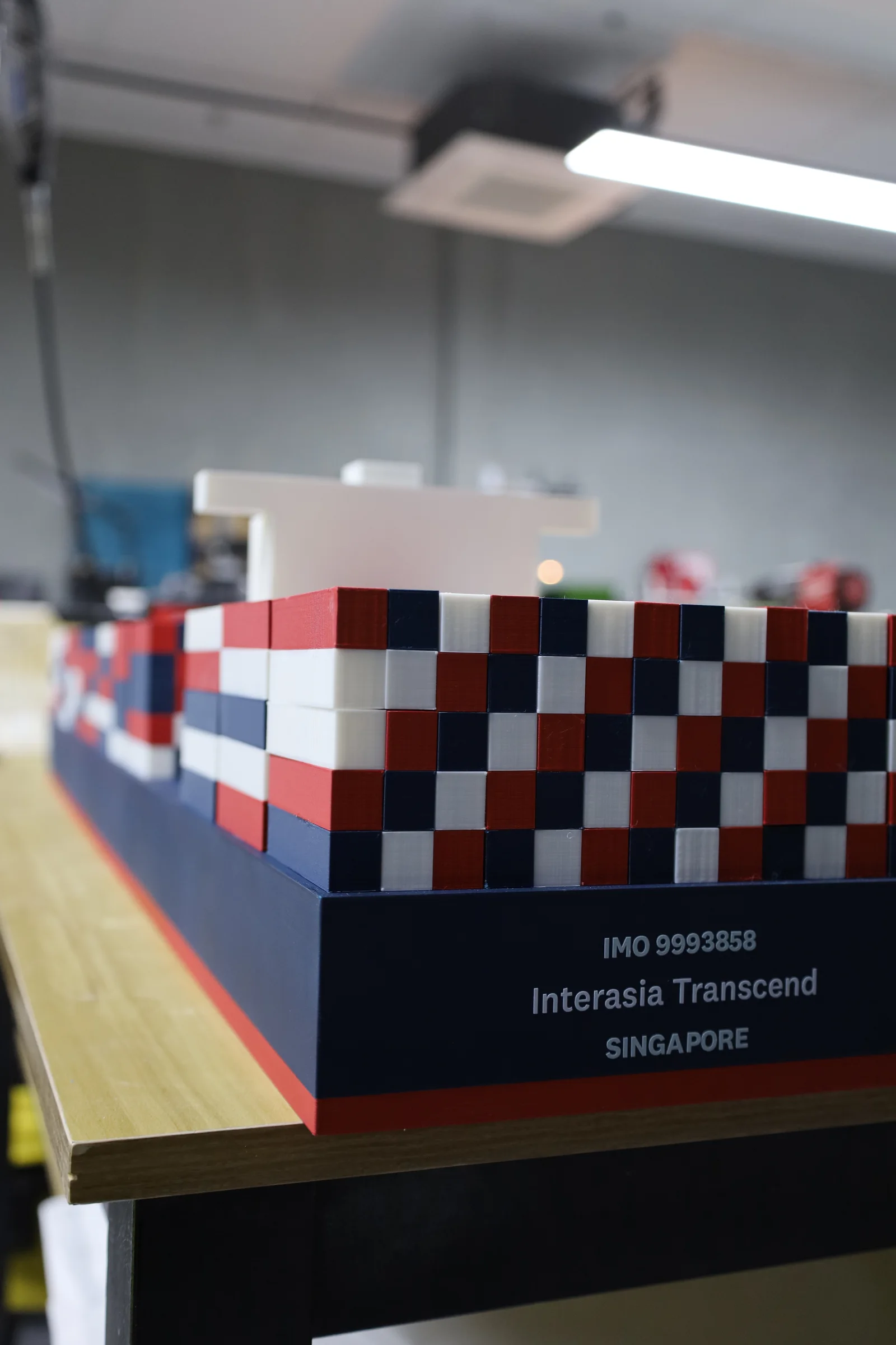
Colour can also be printed in rather than painted on: our Interasia ship model was printed in the line’s red, white and navy filament. Choosing colours for a 3D print covers what each route suits. If you would rather hand over drawings than a file, how architectural scale models are made walks through every stage from print to lit base.
When to switch to resin (stereolithography, SLA)
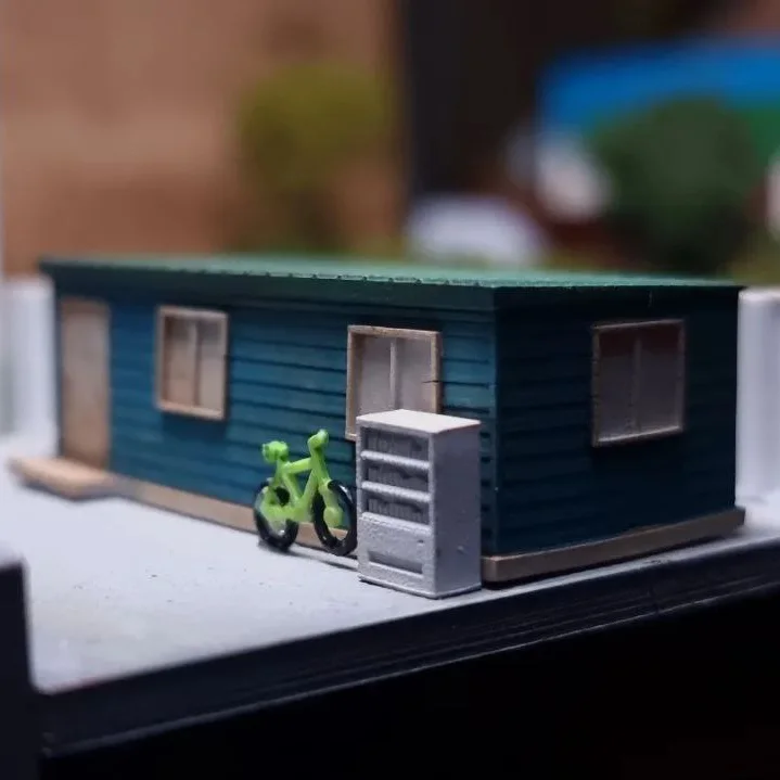
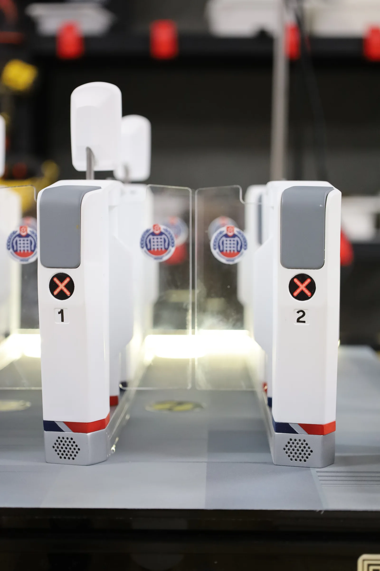
Some detail cannot be thickened to 1 mm without looking wrong: ornament, grilles, fine railings, sculpted fittings. Print those in resin, which builds details down to 0.5 mm with a smoother surface that needs less filling before paint.
- Detail: 0.5 mm, walls 1.0 mm, against 1 mm and 1.2 mm in filament.
- Size: one resin piece can be up to 1700 x 800 x 600 mm.
- Mixed builds: many models print the massing in filament and the fine parts in resin, then paint them to match.
- Hollow parts need drain holes: resin print defects explains where they go.
How resin is priced is on pricing, and the process on our resin printing service.
Frequently asked
How do I design an architectural model for 3D printing?
Keep every detail that must show at least 1 mm thick at model scale, walls at 1.2 mm (2.0 mm where the model is handled or glued), and the file a closed, watertight solid. Then lay floor slabs flat on the print bed, lie loose columns down, and split a building bigger than the printer by floor or wing, with pegs that leave 0.2 mm each side so the pieces line up.
What scale should I use for a 3D printed architectural model?
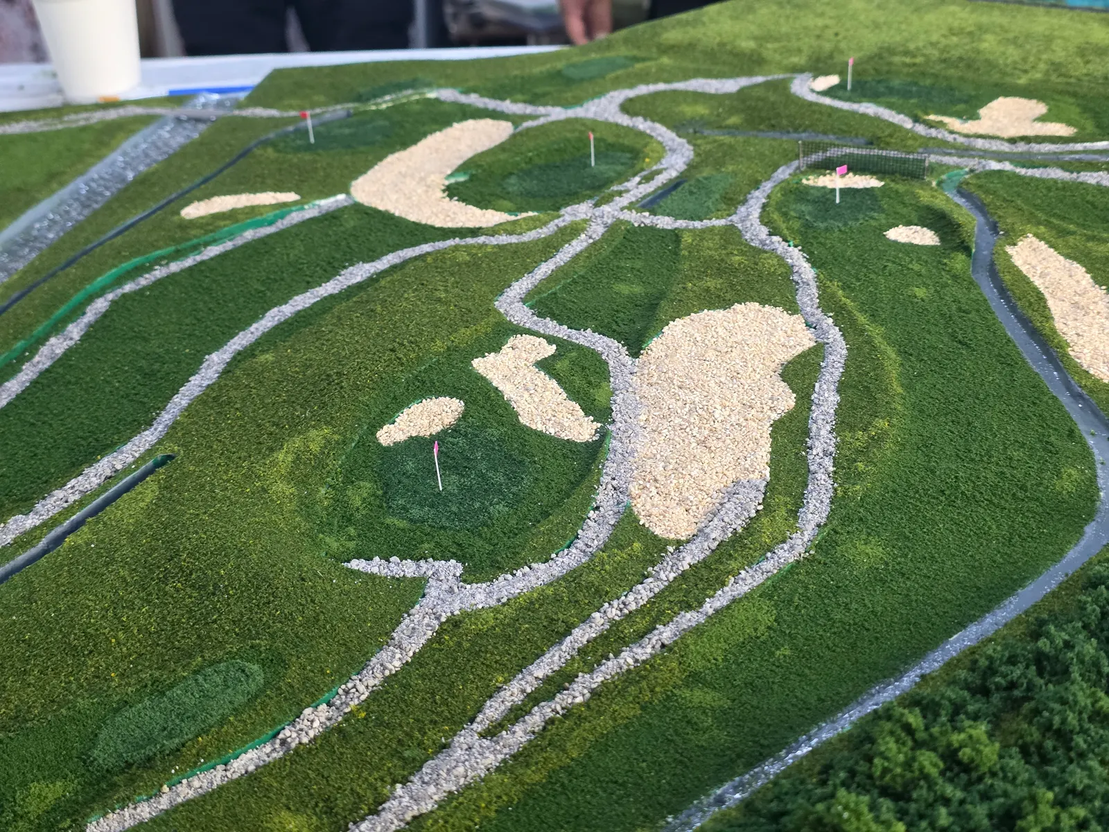
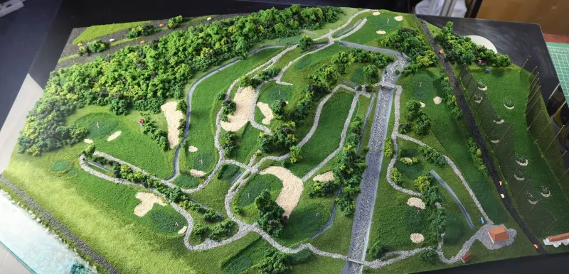
Pick the scale at which your smallest detail that matters is still 1 mm thick, or thicken that detail to 1 mm. Typical choices, not fixed rules, are 1:50 for interiors, 1:100 for a single building, 1:200 for a block, 1:400 or 1:500 for a site and 1:1000 for a masterplan. Our Mandai Golf Course model was built at 1:400 so the whole course sat on one base.
How thin can walls be in a 3D printed architectural model?
Walls should be at least 1.2 mm thick at model scale, and 2.0 mm on anything handled, glued or lifted off, such as a base, a removable floor or a column glued in. Smaller details such as mullions and rails can go down to 1 mm. Window and door openings should be at least 2.0 mm across.
How do I stop windows, railings and mullions disappearing at small scale?
Thicken windows, railings and mullions to 1 mm at model scale instead of leaving them true to scale or dropping them. A 50 mm door frame at 1:100 is only 0.5 mm, too thin to print, but drawn at 1 mm it prints and still reads as a door frame from viewing distance. If a detail cannot be thickened without looking wrong, print that part in resin.
How do I turn a SketchUp, Rhino or Revit model into a printable file?
Before you export from SketchUp, Rhino or Revit, give every wall real thickness: a face or surface with no thickness cannot be printed. Then make each part a closed solid (a solid group in SketchUp, a closed polysurface in Rhino), strip furniture and services you will not see, and export STL, 3MF, OBJ, STEP or IGES in millimetres. Our instant quote takes uploads up to 1 GB.
How do I split a building model into parts, and how big can each part be?
Split a building model where it is bigger than the printer, or where a split makes painting and assembly easier: along a floor, between wings, at a roofline or a facade panel edge. One piece can be up to a 360 mm cube on our desktop printers and 1000 x 1000 x 1200 mm on the large-format one. We recommend where to split and why; the decision is always yours.
How do I join the floors and sections of a building model?
Join the floors and sections of a building model with pegs and sockets that leave 0.2 mm each side, so the pieces line up by themselves. Glue them with two-part epoxy for a joint that never opens, or leave a floor unglued so it lifts off to show the interior. Seams placed on a floor line or a panel edge disappear once the model is filled and painted.
How should I orient a building model on the print bed?
Floor slabs and bases lie flat on the print bed, and loose columns lie down. A filament print is weakest between its layers, so a thin column printed standing up can snap along a layer, while lying down every layer runs its full length. Keep overhangs within 45° of vertical, or put a 45° chamfer under balconies and eaves.
When should I use resin instead of filament for an architectural model?
Use resin (stereolithography, SLA) for detail that cannot be thickened to 1 mm without looking wrong, such as ornament, grilles and fine railings. Resin holds details down to 0.5 mm with a smoother surface, and one resin piece can be up to 1700 x 800 x 600 mm. Many models print the massing in filament and the fine parts in resin.
Can you check my file, or build the whole model for me?
Yes, a person checks every uploaded file before it prints and flags details under 1 mm, walls with no thickness and parts too big to print in one piece, and suggests where to split. If you would rather hand it over, our scale model team works from your drawings and designs, prints, paints, bases and lights the whole model.
Related
-
 GuideHow is an architectural scale model actually made?
 -
 GuideHow do you prepare a 3D model so it prints properly?
 -
 GuideHow do I export and send a 3D file so it prints first time?
 -
 ServiceIndustrial 3D Printing
 -
 ServiceSLA 3D Printing
 -
 ServiceColour Application & Finishing
 -
 ProjectFaceted laser-cut architecture model
 -
 ProjectArchitectural concept model of a courtyard building
 -
 ProjectGolf course diorama for Mandai Executive Golf Course