

Which metal 3D printing defects can you fix in the design?
Five metal 3D printing defects start in the file, not the printer: sideways holes that sag, overhangs that need supports, large flat plates that warp, powder trapped in hollow parts, and faces that must fit but miss. We print metal by selective laser melting (SLM): a laser melts fine metal powder, layer by layer, in stainless steel, aluminium or titanium (for another metal, ask us). Below is each defect, why it happens and the change to make in the model, or have our studio redraw it for you.
Every process’s figures sit side by side in the design rules table. Whether to print the part in metal or machine it from solid is covered in metal 3D printing or CNC machining. Problems that start on the machine rather than in the file are in common problems with 3D printed models.
Sideways holes that sag
What you see: a hole running sideways through the part comes out with a rough, drooping top, more pear than circle.
Why: the top of a sideways hole is a small ceiling with only loose powder under it. A small circle closes over before it can sag. A bigger one has too much roof with nothing holding it up.

Fix it in the design: keep round sideways holes up to 6 mm across. Above that, draw a teardrop: a round hole with a point at the top, so the roof slopes in and builds itself. The smallest hole that prints is 1.0 mm upright and 1.5 mm sideways. A hole that must be an exact size is machined afterwards, as in faces that must fit.
Overhangs that need supports
What you see: the underside of a ledge or a flat ceiling is dull, rough or stepped, with marks where supports were cut away.
Why: each layer can only reach a little past the one below it. A flatter face needs supports, metal scaffolding printed with the part and cut off afterwards. The face they touched always comes out rougher than the rest.

Fix it in the design: keep faces within 45° of vertical, or 35° for 316L stainless steel. Put a chamfer (a flat, angled edge) under a ledge instead of a flat shelf, and turn a flat ceiling inside the part into a peak. Avoid bridges, flat spans between two walls; if you need one, ask us. Where supports can’t be avoided, tell us which faces must stay clean and they go on the others.
Flat plates that warp
What you see: a large flat plate or a thin panel curls up at the edges, or comes off the machine bent.
Why: each layer is melted, then cools fast and shrinks. Across a big flat area that shrinking adds up and pulls the part out of shape. A thick section next to a thin one makes it worse.

Fix it in the design: keep walls and plates an even thickness, and stiffen a panel with ribs rather than making the whole plate thicker. Avoid a large plate that has to print lying flat. Tell us the size and which way the part can stand, and we confirm how it should be printed.
Powder trapped in hollow parts
What you see: a hollow part that rattles, weighs more than it should, or keeps shedding fine grey powder from a channel.
Why: every closed space fills with loose metal powder as the part prints, and powder can only leave through a hole.

Fix it in the design: give every closed cavity two or more powder holes of 5 mm, ideally at opposite ends. Air goes in one and the powder pours out of the other. A sealed cavity cannot be emptied at all, so a person checks every file before it prints and tells you if one is sealed.
Faces that must fit but miss
What you see: a bearing seat, a bore or a sealing face is close but not to size, or a printed thread won’t take a bolt.
Why: as printed, metal holds ±0.2 mm up to 50 mm, then ±0.4% of the length, and its surface is slightly rough. That suits brackets and housings, not a face that has to fit.

Fix it in the design:
- Faces that must fit: draw them with 0.5 mm of extra metal, and we machine it off after printing. Mark which faces matter and the size each needs; the rest stays as printed.
- Threads: tapped after printing. Draw the hole at the thread’s core size (the narrower hole the thread is cut into) and tell us the thread, for example M6.
- Moving parts or parts printed already assembled: leave 0.3 mm on each side.
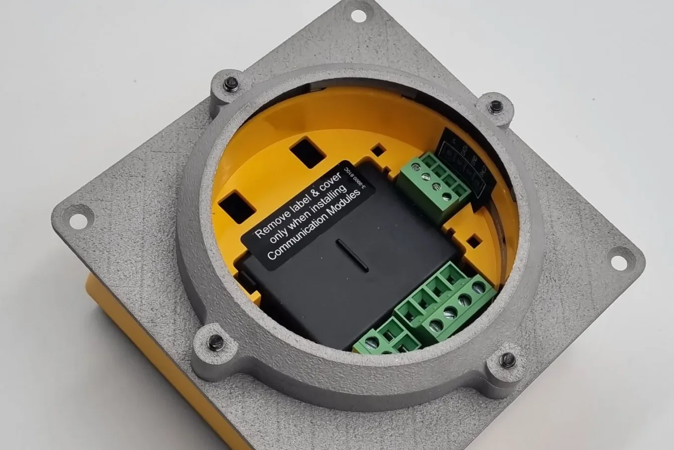
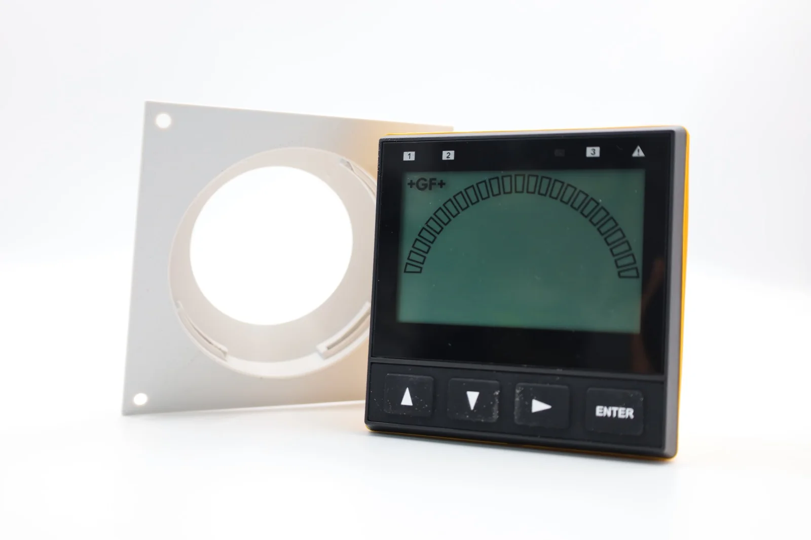
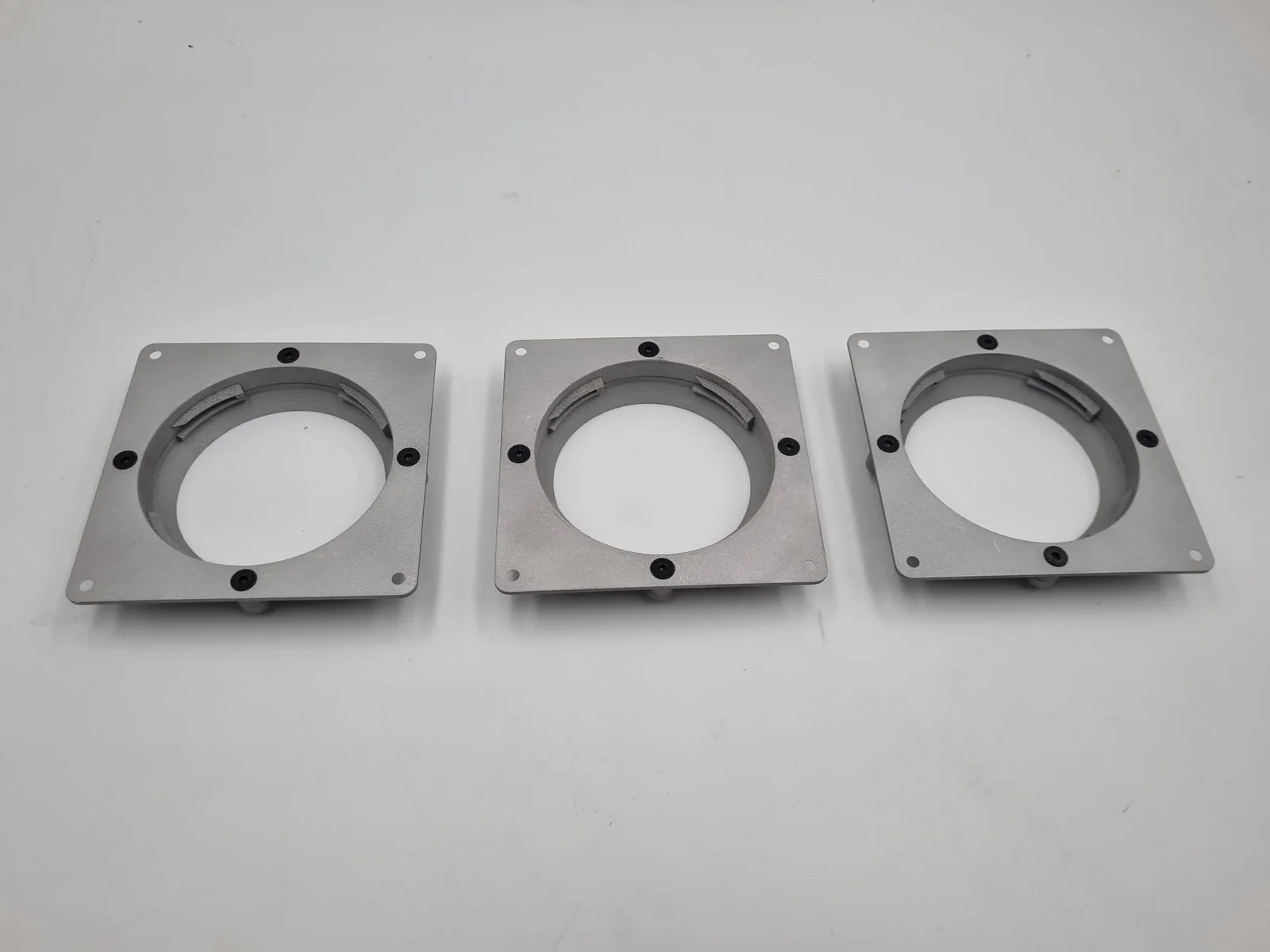
The fits for every process are in 3D printing tolerances and clearances. The cheapest way to check a fit is a plastic print first: for our flow meter panel mount we tuned the bore, the retaining tabs and the screw positions in PLA against the real meter, then printed it in metal.
Frequently asked
What overhang angle can metal 3D printing do without supports?
Metal 3D printing builds faces within 45° of vertical without supports, or within 35° for 316L stainless steel. A flatter face needs supports, which are printed in metal and cut off afterwards, so the face they touched comes out rougher than the rest. A chamfer under a ledge, or a peak instead of a flat ceiling, lets the part build itself.
Can you print a sideways hole in metal without supports?
A round sideways hole up to 6 mm across prints clean in metal without supports. Above 6 mm, draw it as a teardrop, a round hole with a point at the top, so its roof slopes in and builds itself. The smallest sideways hole is 1.5 mm; an upright hole can go down to 1.0 mm.
How thin can a wall be in metal 3D printing?
Design metal walls at 1.0 mm or thicker, 1.2 mm for a thin wall standing on its own and 2.0 mm for anything handled or knocked. Raised or recessed detail can go down to 0.5 mm, and lettering needs strokes of 0.6 mm and letters at least 3 mm tall.
Why do large flat metal parts warp?
Large flat metal parts warp because every layer shrinks as it cools, and across a large flat area that shrinkage adds up and pulls the part out of shape. Keep sections an even thickness, stiffen panels with ribs rather than a thicker plate, and tell us the size so we can confirm how it should stand on the machine.
How do you get powder out of a hollow metal part?
A hollow metal part needs two or more powder holes of 5 mm, ideally at opposite ends of each cavity. Air goes in one and the loose powder pours out of the other. A sealed cavity cannot be emptied at all, so the file has to have the holes before it prints.
How much extra metal should I leave on a face that must fit?
Leave 0.5 mm of extra metal on a face that must fit, and we machine it off to size after printing. As printed, metal holds about ±0.2 mm up to 50 mm, then ±0.4% of the length, which suits brackets and housings but not a bearing seat or a sealing face. Threads are tapped after printing, not printed.
A part you printed for me has one of these defects. What now?
Tell us, with a photo if you can. A person checks every file and every part before it leaves us, so it should not happen. Where the fault is in the printing, we typically reprint it free, case by case; a defect that was in the file is one the check should have flagged, so we look at it the same way.
Can you check or fix my file before it prints?
Yes, a person looks over every uploaded file before it prints and flags anything that will not print as drawn. If it needs more than a tweak, our design service can redraw the model so it prints properly, or build one from a sketch or a sample if you have no file.
Related
-
 GuideMetal 3D printing or CNC machining: which does your part need?
 -
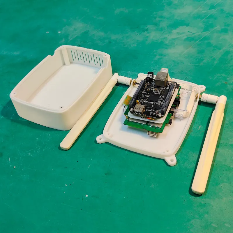 GuideHow do you prepare a 3D model so it prints properly?
 -
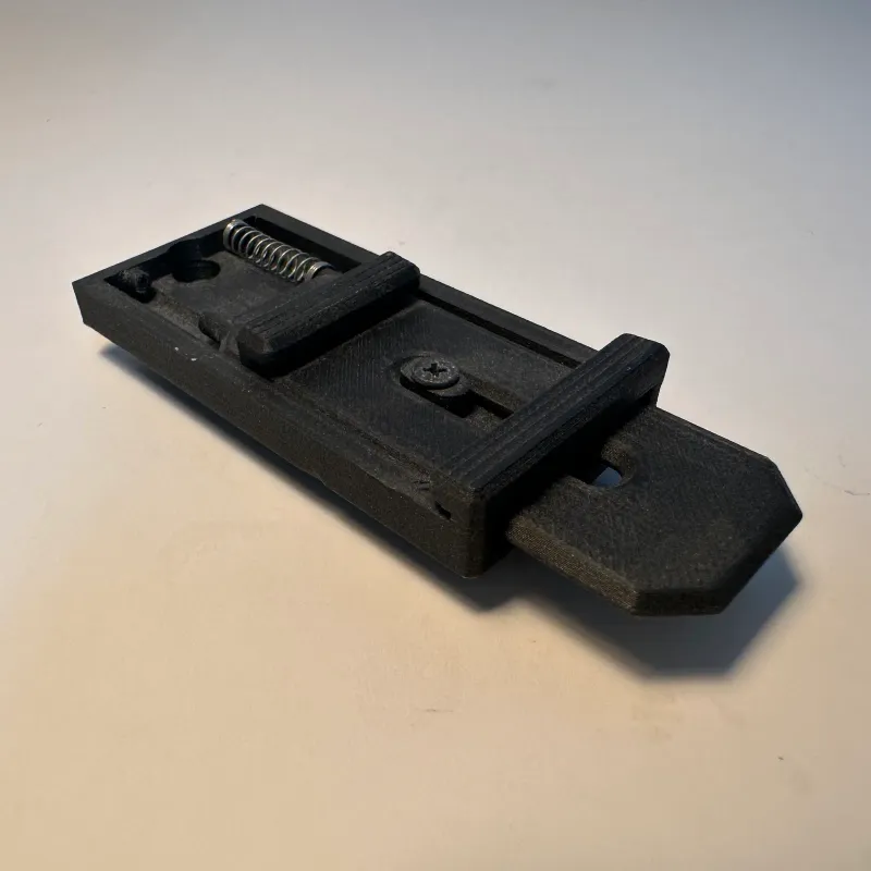 GuideHow much clearance do 3D printed parts need to fit together?
 -
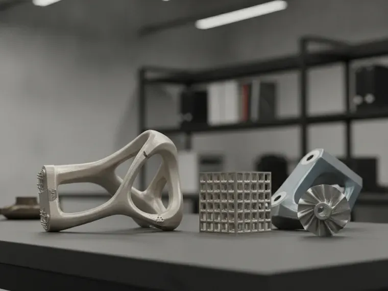 ServiceMetal 3D Printing
 -
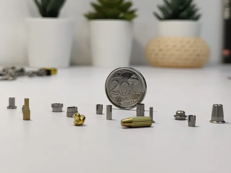 ServiceCNC Machining
 -
 ServiceProduct Development & Prototyping
 - ProjectCustom Stainless Steel Housing
- ProjectSpring-Loaded Quick-Release Rail
-
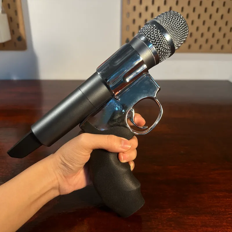 ProjectMic Stand Revolver