

What is SLM metal 3D printing, and how does it work?
On this page
- SLM metal 3D printing at a glance
- How SLM works: a laser melts metal powder, layer by layer
- Supports: metal needs them, nylon does not
- After printing: cut free and supplied as printed
- Surface as printed: grainy, like fine sandpaper
- Finishes: as printed, blasted, machined or polished
- Size and lead time: up to 420 x 420 x 450 mm, about 10 to 12 working days
- Design rules for SLM: the figures that matter most
- When another route suits better: CNC, sheet metal or plating
- Frequently asked
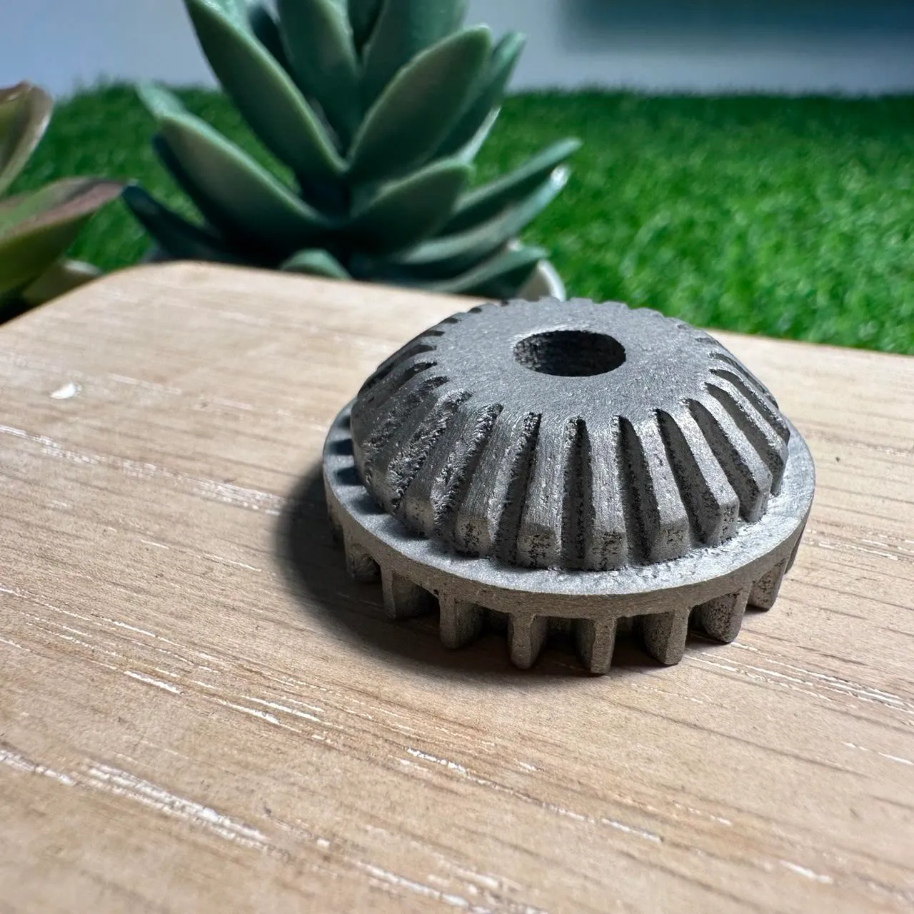
SLM metal 3D printing, short for selective laser melting, builds a solid metal part straight from your 3D file. A laser melts fine metal powder, one thin layer at a time, inside a chamber of inert gas, and each layer fuses to the one below. In Singapore we use it for metal 3D printed parts in stainless steel, aluminium and titanium that must take heat, load or wear, in shapes that are hard to machine.
SLM metal 3D printing at a glance
| What you want to know | SLM metal 3D printing |
|---|---|
| What it does | Melts metal powder with a laser, layer by layer, into a solid metal part |
| Metals | 316L and 17-4PH stainless steel, AlSi10Mg aluminium, Ti6Al4V titanium; other alloys on request |
| Largest single part | 420 x 420 x 450 mm |
| Accuracy as printed | About ±0.2 mm up to 50 mm, then ±0.4% of the length |
| Faces that must fit | Printed 0.5 mm oversize, then machined to size |
| Surface as printed | Grainy and matte, rougher where supports touched |
| Heat treatment | None, not even stress relief: parts are supplied as printed |
| Lead time, normal-size part | About 10 to 12 working days |
| Best for | Brackets, mounts, manifolds and parts with internal channels or lattices |
| Not the best choice for | Simple solid blocks, the tightest tolerances, or parts that only need to look like metal |
Lead time is a rough guide in working days for a part about 10 to 15 cm across. Bigger parts and extra finishing take longer, so check with us.
How SLM works: a laser melts metal powder, layer by layer
SLM belongs to the family the standards call powder bed fusion: heat fuses chosen areas of a bed of powder. In SLM the heat is a laser and the powder is metal.
- Slicing. Software cuts your 3D model into layers 0.03 to 0.04 mm thick.
- Spreading. A blade spreads one layer of fine metal powder over a steel build plate.
- Melting. The laser traces that layer’s shape and melts the powder, fusing it to the layer below.
- Repeat. The plate drops by one layer, fresh powder goes on, and the laser melts the next slice.
The chamber is filled with an inert gas, one that does not react with the hot metal. The metal melts fully, so the finished part is solid metal, not glued or pressed powder. You may also see it called DMLS (direct metal laser sintering) or laser powder bed fusion: the idea is the same.
Supports: metal needs them, nylon does not
In nylon powder printing (SLS or MJF), the loose powder holds the part up. Metal is different. Each layer is melted, then cools fast and shrinks, and that shrinking pulls the part out of shape. So a metal part is built on supports: thin metal scaffolding that anchors it to the build plate and carries the heat away.
- Overhangs: faces within 45° of vertical build themselves (within 35° for 316L stainless steel). Anything flatter needs supports.
- The cost of supports: the faces they touch come out rougher than the rest. Tell us which faces must stay clean and the supports go on the others.

After printing: cut free and supplied as printed
When the build finishes, the part is still fused to the steel build plate. We cut it free, remove the supports and clean up the faces they touched. Loose powder is emptied from any hollow space, which is why a cavity needs powder holes (see the design rules below).
We supply metal parts as printed, with no heat treatment of any kind, not even stress relief. That suits most brackets, housings and mounts. If your part must be heat-treated, for example to bring 17-4PH stainless steel to full hardness, tell us before you order.
Surface as printed: grainy, like fine sandpaper
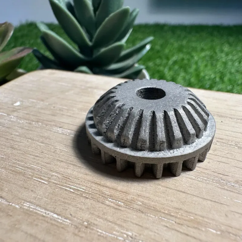
Every SLM part leaves the machine with a grainy, matte surface: the edges of the melted powder grains show. Faces that touched supports are rougher still. As printed, a part holds about ±0.2 mm up to 50 mm, then ±0.4% of the length, which suits brackets and housings but not a bearing seat.

Finishes: as printed, blasted, machined or polished
You choose how far to take the surface:
- As printed: grainy and matte. Fine for hidden brackets and internal parts.
- Bead or sand blasted: an even, matte surface with the loose grains blasted off.
- Machined faces: leave 0.5 mm of extra metal on any face that must fit, and we machine it to size on our CNC machines after printing. Mark which faces matter; the rest stays as printed.
- Polished: a smooth, bright surface.
Size and lead time: up to 420 x 420 x 450 mm, about 10 to 12 working days
A single metal part can be up to 420 x 420 x 450 mm. For anything bigger, send the file and we look at printing it in pieces or using another process. A normal-size part, about 10 to 15 cm across, takes about 10 to 12 working days; bigger parts and extra finishing take longer, so check with us when you have a deadline. Our lead time guide explains why.
We print 316L and 17-4PH stainless steel, AlSi10Mg aluminium and Ti6Al4V titanium, and other alloys on request. How they compare on weight, strength, rust and heat is in which metal to 3D print in.
Design rules for SLM: the figures that matter most
Design to these and the part prints as drawn:
- Walls: 1.0 mm at least, 1.2 mm for a wall standing on its own, 2.0 mm for anything handled or knocked.
- Holes: 1.0 mm upright and 1.5 mm sideways at the smallest. Keep round sideways holes up to 6 mm; above that, draw a teardrop (a point at the top) so the roof builds itself.
- Hollow parts: two or more powder holes of 5 mm, at opposite ends, so the loose powder can be emptied.
- Fine detail: raised or recessed detail down to 0.5 mm; lettering with 0.6 mm strokes and letters at least 3 mm tall.
- Threads: tapped after printing, not printed. Draw the hole at the thread’s core size and tell us the thread.
- Moving parts printed together: 0.3 mm gap on each side.
Each rule, with its fix, is in metal 3D printing defects you can fix in the design, and every process side by side is in the design rules table.
When another route suits better: CNC, sheet metal or plating
SLM earns its place when a part needs metal and a shape that is hard to cut. Otherwise, another route is often better:
- Simple solid parts, or the tightest fit: CNC machining cuts the part from a solid block, holds ±0.05 mm and leaves a cleaner surface. Our metal printing or CNC guide shows how to tell.
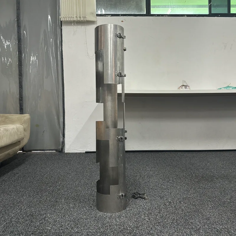
- Thin shells and enclosures: cut and bent sheet metal suits a plain box or cylinder better than a print, as with this stainless steel housing.
- Many identical parts: for a large batch, ask us. Casting or machining can work out cheaper per part than printing each one.
- It only has to look like metal: a painted or plated plastic print gets the look for far less.
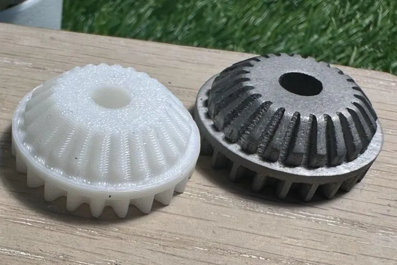
Whichever route, a plastic test print is the cheapest way to check the fit first, as we did with this gear:
Frequently asked
What is SLM 3D printing?
SLM (selective laser melting) is a 3D printing process that builds solid metal parts by melting fine metal powder with a laser, one thin layer at a time, inside a chamber of inert gas. It makes parts in stainless steel, aluminium and titanium straight from a 3D file, including shapes a cutting tool cannot reach, such as internal channels.
Is SLM the same as DMLS?
In practice, yes: SLM (selective laser melting) and DMLS (direct metal laser sintering) are different names for the same idea, a laser fusing a bed of metal powder layer by layer. The standards group both under powder bed fusion. Whichever name your drawing uses, send the file and we print it the same way.
Do you heat-treat metal 3D printed parts?
No, we supply metal 3D printed parts as printed, with no heat treatment of any kind, not even stress relief. That suits most brackets, housings and mounts. If your part must be heat-treated, for example to make 17-4PH stainless steel fully hard, tell us before you order so we can talk it through.
Why does metal 3D printing need supports when nylon printing does not?
Metal needs supports because each layer is melted and then cools and shrinks fast, which pulls the part out of shape unless it is anchored. Supports hold it to the build plate and carry the heat away. In nylon powder printing the loose powder holds the part up, so no supports are needed.
How accurate is SLM metal printing?
As printed, SLM metal holds about ±0.2 mm up to 50 mm, then ±0.4% of the length. That suits brackets and housings. For a face that must fit, such as a bore or a sealing face, leave 0.5 mm of extra metal and we machine it to size after printing.
How smooth is a metal 3D print?
A metal 3D print is not smooth straight off the machine: it comes out grainy and matte, a little like fine sandpaper, and faces that touched supports are rougher still. Bead or sand blasting evens it out, machining makes a face flat and exact, and polishing makes it smooth and bright.
How long does SLM metal 3D printing take?
An SLM metal part takes about 10 to 12 working days at normal size, about 10 to 15 cm across. Treat that as a rough guide: bigger parts, and extra work such as machined faces or polishing, take longer, so check with us when you have a deadline.
Is SLM metal printing cheaper than CNC machining?
SLM metal printing is usually not cheaper than CNC machining for a simple solid part, where CNC is often the better-value route. Metal printing earns its cost when the shape is hard to cut, such as internal channels, lattices or several parts merged into one. Send the file and we tell you which route suits it.
Related
-
 GuideStainless steel, aluminium or titanium: which metal to 3D print?
-
 GuideWhich metal 3D printing defects can you fix in the design?
-
 GuideMetal 3D printing or CNC machining: which does your part need?
-
 ServiceMetal 3D Printing
-
 ServiceCNC Machining
-
 ServiceIndustrial 3D Printing
-
 ProjectFlow Meter Panel Mount for Bencontrol Technologies
-
 ProjectCustom Stainless Steel Housing for an SAF Missile Manpack
-
 ProjectElectronic Parts Holding Jig for Sanwa Intec