

3D printed RFID jigs for ST Engineering
A small RFID jig for ST Engineering, a lever that tips under weight, taken through three revisions, then printed 133 times with a laser-cut black EVA base grid and tool plate.
- Client
- ST Engineering
- Also used
- Laser cutting & stickers
- What it is
- A small RFID jig, a lever that tips under weight
- What we did
- Three design revisions, test prints, 133 printed jigs and laser cutting
- What the client got
- 133 jigs, a black EVA base grid and a top tool plate
- RFID jigs printed in PLA
- 133
- Design revisions, from a boxed see-saw to a flat lever
- 3
- Long in the final revision, 35 mm wide and 12.2 mm tall
- 70 mm
- Wide base grid, 510 mm deep, seven rows of 19 cells
- 695 mm
What we brought
What we can do
Smaller with each revision
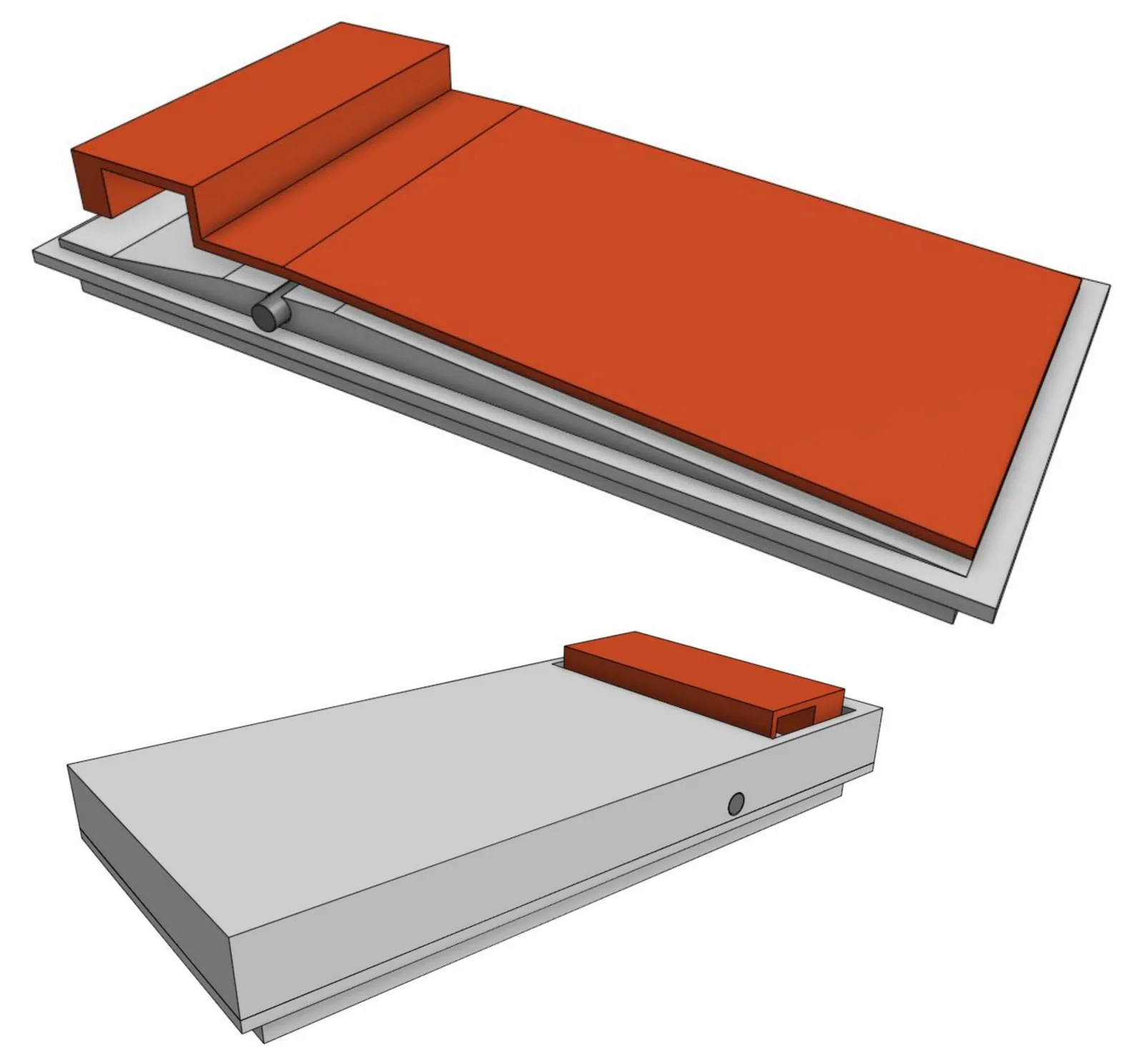
The first jig was a see-saw lever inside a case. By the third revision it was a 70 by 35 mm base with a flat lever on a pin, with a weight sensitivity of 1 g or less as the aim.
How we look after you
Tried in print before the run
Each of the first two rounds came with a test print in PLA, so the lever could be tried in the hand before we printed 133.
What you get
Printed parts and cut foam from one studio
We also drew and laser-cut the black EVA base grid and the top tool plate, so the jigs, the grid and the tool plate all came from one place.
Gallery
The whole project at a glance. Drag or swipe to browse; tap a picture to enlarge it.
1 / 9
-
The finished piece
-
Three revisions · Revision 0RenderRevision 0: case, lever and base.
-
Three revisions · Revision 1RenderRevision 1: smaller, with the RFID tag inside.
-
Three revisions · Revision 2RenderRevision 2: 70 by 35 mm.
-
RenderThe lever on its pin, from the side.
-
Printed and laser cutRenderThe base grid, rendered.
-
DrawingThe base grid, 695 by 510 mm.
-
DrawingA tool plate sheet, a pocket for each tool.
-
DrawingA second tool plate sheet.
The build
How we built it
5 steps, from the brief to the finished piece. Pick a step to jump to it.
The brief
Step 1 of 5
- What it does
- A lever that tips down under weight
- Our scope
- Design for manufacture over three revisions, test prints, 133 printed jigs, laser cutting
At Additive Inn, our 3D printing studio in Singapore, we designed and made an RFID jig for ST Engineering. It is a small lever that pivots like a see-saw and tips down under weight. Once the design was settled we printed 133 of them, and laser-cut a black EVA base grid and a top tool plate.
Three revisions
Step 2 of 5
We took the jig through three revisions. The second round asked for a smaller actuator, with a weight sensitivity of 1 g or less as the aim.
-
Revision 0
A case, a lever and a base. The lever sits on a sloped base inside the case and pivots like a see-saw, tipping down under weight.
Render
-
Revision 1
Much smaller, 76 by 31 mm: an orange lever with a domed end pivots inside a slim case, with the RFID tag shown in place.
Render
-
Revision 2
A low base 70 by 35 mm with a flat orange lever on a pin across it: 10 mm tall, and 12.2 mm with the lever.
Render +1 more
Printed and laser cut
Step 3 of 5
We made a test print in PLA with each of the first two rounds. Then we printed 133 jigs in PLA in our studio, and laser-cut a base grid and a top tool plate from black EVA foam to our drawings.
The grid and the tool plate
Step 4 of 5
In the final design the lever sits on a pin across the printed base. The base grid is cut with 133 cells, seven rows of 19, the same number as the jigs we printed, and the top tool plate has a pocket shaped to each tool.
The final build
Step 5 of 5
ST Engineering received 133 printed RFID jigs, the black EVA base grid and the top tool plate.
More product development
See all product development →-
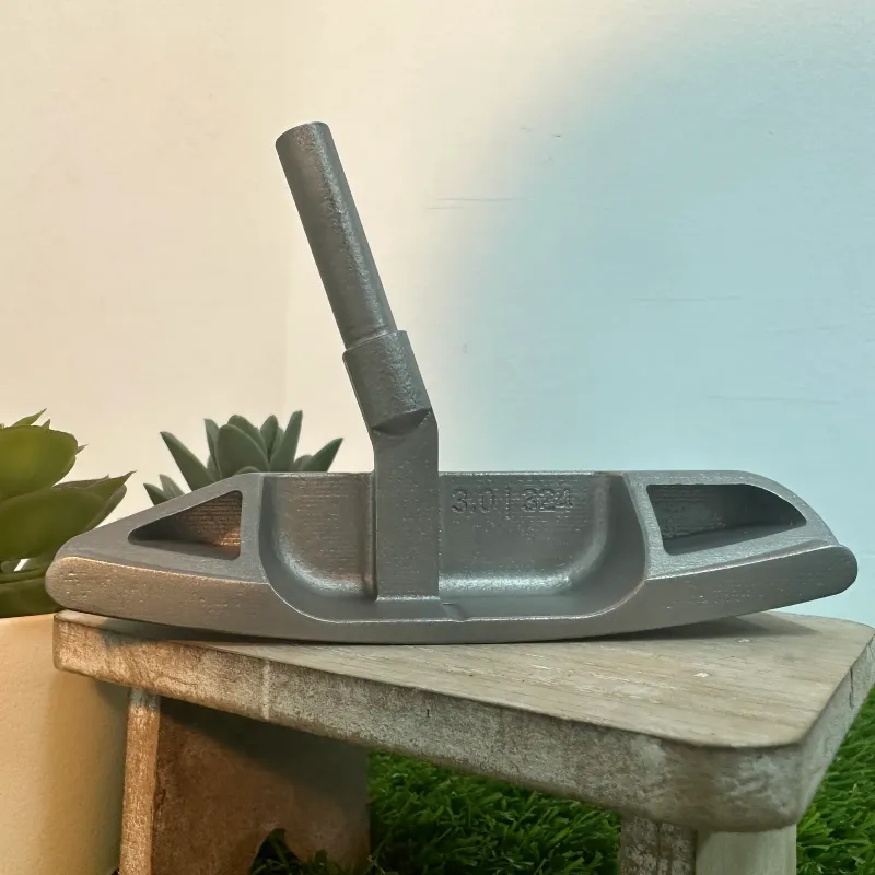 Private client Custom 3D printed golf putter head A putter head designed from scratch: a 3-degree loft, two pockets that set its mass, and the loft and mass marked on the back.
-
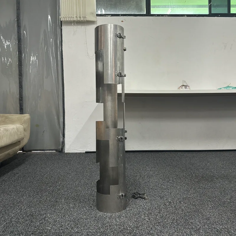 18 DA Bn, Singapore Armed Forces Custom stainless steel housing for an SAF missile manpack A stainless steel carry sleeve for an RBS 70 missile, drawn from the SAF team's own sketch, rolled from sheet and closed with toggle latches.
-
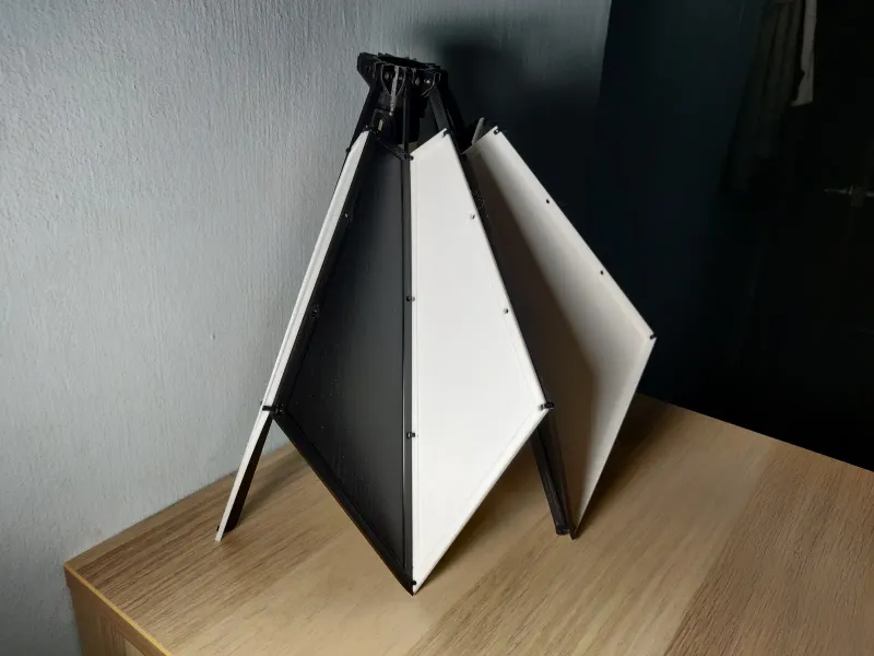 Collapsible shelter prototype A working scale model of a lamp post shelter for pedestrian crossings, 3D printed with hinged panels that fold away and open by hand.