

Kayak rudder cable retractor, reverse engineered
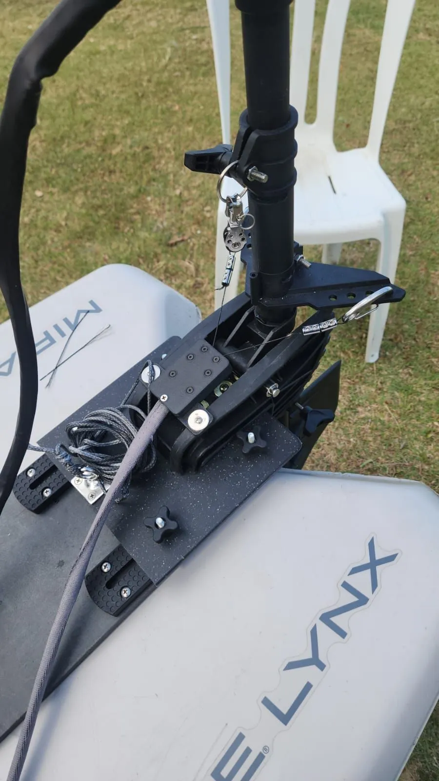
A new rudder cable retractor for a private client's kayak, rebuilt in CAD from the worn original as a stiffer, serviceable housing in carbon-fibre PETG, then fitted and tested by the client.
- Client
- A private client
- What it is
- The housing that guides a kayak's rudder lines
- Started from
- The client's worn original retractor
- What we did
- Reverse engineering, CAD redesign, prototype and the final sets
- Sets of retractors in the order
- 2
- Grade of the stainless steel hardware
- 316
- Days from the brief to the CAD redesign
- 3
What we brought
What we can do
Rebuilt from the worn original
We took the client's original retractor apart, measured its housing and pulleys and rebuilt them in CAD, with the mounting flange matched to the client's template.
How we look after you
Made to be serviced
The housing is held together with marine-grade stainless steel bolts and nuts, never screws into plastic, so it can be opened and closed again and again.
What you get
Fitted and tested
The client fitted the prototype to the kayak and tested it before we made the final retractors.
Gallery
The whole project at a glance. Drag or swipe to browse; tap a picture to enlarge it.
1 / 12
-
The finished piece
-
On the kayak, with the rudder.
-
The rudder and its lines, from the side.
-
A rudder line running through the housing.
-
The briefThe original retractor we started from.
-
Taken apart, with its pulleys and pins.
-
The original, from the end.
-
Design and prototyping · Revision 0RenderRevision 0, sent on 13 February.
-
Design and prototyping · Revision 1RenderRevision 1, exploded.
-
RenderRevision 1, cut away to show the lines over the pulleys.
-
Printing the prototypePacked for the client to collect.
-
Build and assemblyThe assembled prototype, bolted together.
The build
How we built it
5 steps, from the brief to the finished piece. Pick a step to jump to it.
The brief
Step 1 of 5 · 10/02/2026
- Part
- Kayak rudder cable retractor, housing and pulleys
- Started from
- The client's original retractor and a template for the mounting holes
- Material
- Carbon-fibre PETG for stiffness and UV resistance
- Hardware
- 316 marine-grade stainless steel bolts and nuts
- Our scope
- CAD redesign, a prototype, 3D printing and assembly of two sets
At Additive Inn, our 3D printing studio in Singapore, we reverse engineer parts that can no longer be bought. A private client's kayak had a worn rudder cable retractor, the housing that guides the rudder lines. We were to rebuild it as a reinforced housing that can be taken apart and serviced, with its pulleys and a mounting flange made to the client's template, and make two sets.
Design and prototyping
Step 2 of 5 · 13/02/2026
We rebuilt the retractor in CAD as a two-part housing on a wide mounting flange, with the flange holes matched to the client's template. The two rudder lines run through the housing over a pair of pulleys, each turning on a pin, and the halves are bolted together through the housing.
The first design went to the client as a deck on 13 February. The client came to our studio the same afternoon with the rudder line, so we could check how it runs inside the housing, and we updated the design that day.
-
Revision 0
The first redesign, a two-part housing with two printed pulleys, bolted with M3 stainless steel hardware, 52 x 91 mm on its flange.
Render
-
Revision 1
Reworked the same day, after the client showed us how the rudder line runs inside the original.
Render +1 more
Printing the prototype
Step 3 of 5 · 16/02/2026
We printed a prototype in carbon-fibre PETG on our FDM printers, the housing, lid, flange and pulleys, and assembled it to check the line ran through it. It was packed for the client on 19 February.
Build and assembly
Step 4 of 5
Every joint in the housing is a bolt through to a nut, in 316 marine-grade stainless steel, so the plastic never carries a screw thread and the housing can be opened for servicing.
The final build
Step 5 of 5 · 26/05/2026
The client fitted the prototype on the kayak and tested it. Once it had proved itself, we made the final retractors with stainless steel hardware, ready for collection on 26 May.
More product development
See all product development →-
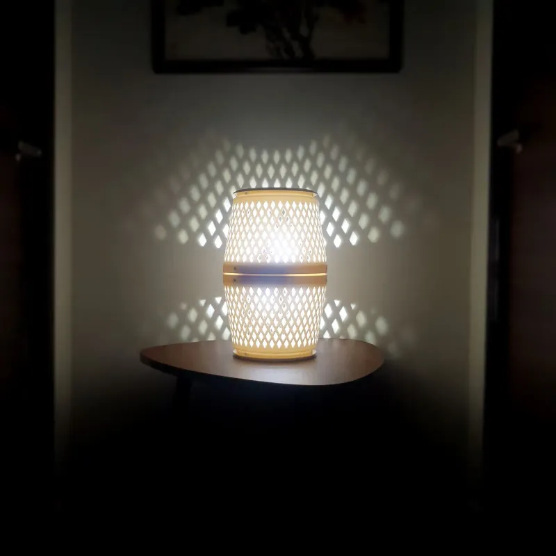 Apollo Envirotec Air purifier lamp for Apollo Envirotec An air purifier that doubles as a lamp for Apollo Envirotec: we designed the housing around its electronics and printed each prototype in our studio.
-
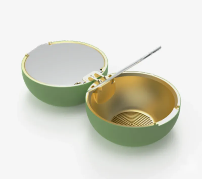 A beauty brand Compact powder case, designed for manufacture A round compact powder case for a beauty brand, taken from a first idea to a design a factory can make, over four revisions.
-
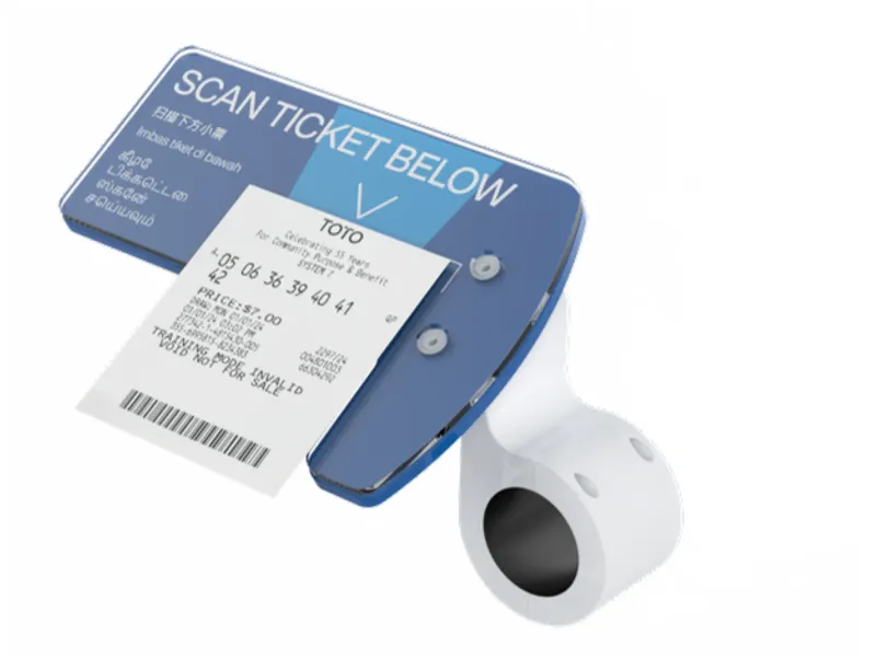 Ticket holder for Singapore Pools tablet kiosks A ticket holder for Singapore Pools that clips onto a wall-mounted tablet kiosk and shows customers where to place their ticket to be scanned.