
A Guide: Designing Architectural Models for FDM Printing

This guide outlines key technical considerations when preparing architectural models for FDM Printing.By following these DOS and DON’TS , you can avoid costly iterations and ensure your designs are both visually accurate and physically manufacturable.
1. Master the "Watertight" Mesh
For a 3D printer to understand your model, it must be a closed volume, also known as manifold geometry.
The Concept: If you were to "pour water" into your 3D model, it should not leak.
The Problem: Architectural software like SketchUp or Rhino often creates "paper-thin" walls or overlapping internal faces.
The Fix: Ensure every wall has a thickness (min. 0.8mm to 1.2mm). Use Boolean Union commands to merge overlapping volumes into a single continuous "skin."
2. Design for the 45-Degree Rule
FDM printers cannot print in mid-air. They need a layer underneath to support the next one.
Overhangs: Any angle greater than 45° from the vertical will likely require support material, which can leave a messy surface finish when removed.
Architectural Strategy: Use chamfers or 45° angled supports under balconies and eaves. This allows the printer to "self-support" the structure, resulting in a cleaner look without wasted plastic.
3. Scaling and Minimum Feature Size
When you scale a building down to 1:50 or 1:100, fine details like window mullions or railings often become too thin to print.
The Math: If your printer has a $0.4mm$ nozzle, it cannot physically print a railing that scales down to $0.1mm$.
The Solution: You must exaggerate small details. Thicken railings, door frames, and window dividers until they are at least two nozzle widths wide (roughly $0.8mm$ to $1.0mm$) to ensure structural integrity.
4. Strategic Orientation & Bed Adhesion
The way you place your model on the print bed determines its strength and surface quality.
Orientation: Large flat surfaces (like the ground floor slab) should always be placed directly on the build plate.
Z-Axis Strength: FDM prints are weakest at the layer lines. If you have tall, thin columns, consider printing them separately lying down and gluing them in later for maximum strength.
5. Modular Assembly: Don't Print Everything at Once
For complex buildings, printing the entire structure as a single piece is risky. If the print fails at 90%, you lose everything.
Sectional Printing: Break the building down by floor levels or wings.
The Benefit: This allows you to show interior floor plans to clients and makes it easier to clean out support material from deep interior rooms.
Here are some examples of not following the GOLDEN RULES

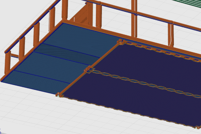
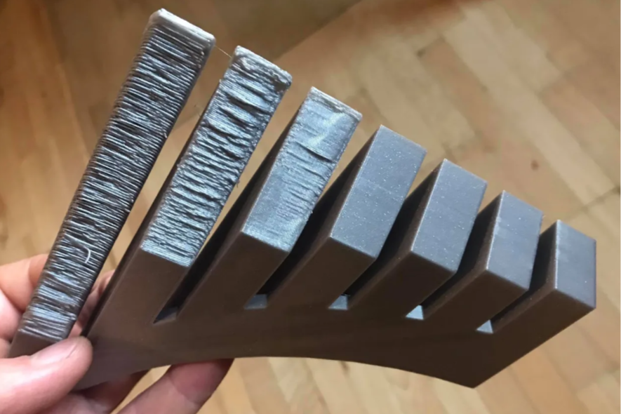
Long, thin rods or railings may cause Z-wobble issues during printing. This can result in the part breaking off mid-print or printing with blobs and imperfections along the railings.

Thin walled structures has a high chance for printing defects.

Thin walls can cause holes and pits to form at the Z-seamline.

Thin walled structures are not strong especially in the direction parallel to the layer lines.
1. Bottom isn’t flat.
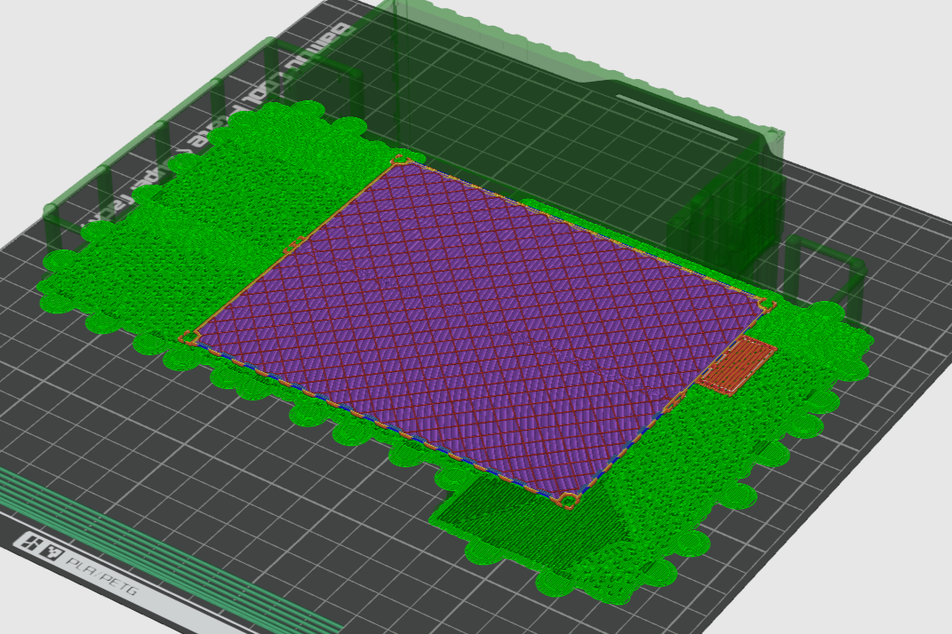
2. Too many supports generated.
3. Poor surface finish after support removal.
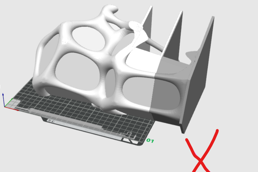
Large models
The file is too big for the print bed, it needs to be cut down into smaller pieces.

Stay Within the FDM Build Volume
Our FDM printers have a maximum print bed capacity of 350mm x 350mm x 350mm (X × Y × Z):
- Any component exceeding this size must be split and reassembled post-print using connectors or adhesives. Always consider the orientation of parts to best fit within these bounds.
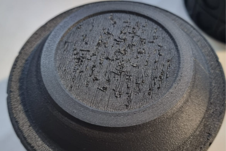
If the overhang angel exceeds 45°, there will be significant filament drooping defects. Supports must be used on any steeper angle but it would negatively affect the surface finish of the overhang.
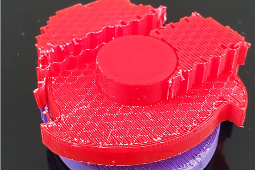
Poor surface finish after support removal.
For small and fine details SLA is the best option as compared to FDM.
Opt for SLA (resin-based) printing for Small or Highly Detailed Components
If your model includes:
- Fine detail <1mm
- Intricate façades or complex design like ornaments
- Small-scale structures (e.g., railings, grills)
- We recommend switching to SLA printing, which provides higher resolution and better surface detail as compoared to FDM. However do keep in mind that SLA printing may be more costly.
👎DON’T: Common Mistakes to Avoid
Don’t merge all the elements into a single mesh:
- Makes slicing and orientation difficult.Don’t assume scaling down will preserve detail:
- Thin elements may disappear or distort.Don’t use unsupported file types or unoptimized exports:
- Make sure you export in .STL, .OBJ, .STEP, or .3MF formats with the correct units (mm).
Final Checklist before submitting for a quote.
✅ Are your walls ≥ 1 mm thick?
✅ Is every level, furniture piece, or structure a separate part?
✅ Have you simplified any complex geometries like mesh or grill?
✅ Does your design avoid severe overhangs (>45°)?
✅ Is your file manifold and error-free?
✅ Have you checked if SLA would better suit intricate components?
✅ Is your model within the 230x230x240mm build volume?
✅ Have you exported your file in an accepted format (.STL, .OBJ, .STEP, .3MF)?
✅ Are your files scaled correctly?
Need a second look before printing?
We offer free printability analysis for all submissions. Upload your files to our instant quotation software for a quote and our team will evaluate them for FDM compatibility!
Alternatively, look for us for 3D design/modeling services.